 A LEVEL COMPUTING
 ALU and Registers
 Theory
2. Buses
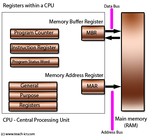
The picture below shows two elements called the 'Data Bus' and the 'Address Bus'

A 'bus' consists of a number of parallel wires (conductors). And each wire handles a single data bit, so it is either at logic 1 (true) or logic 0 (false).
Control Bus
The CPU needs to receive and send control information between other parts of the computer. For example there is a control line between the power supply and the CPU that tells the CPU to boot up once the power supply is steady enough. There is another control line that handles external interrupts and so on. Collectively these lines are called the control bus.
Data Bus
The data bus in a standard (Von Neumann) CPU handles both data and instructions. The purpose of the data bus is to allow data to pass from one area to another. The one above is shifting data between the CPU and main memory. But there are also internal data buses to move information around.
The width of the bus determines how many bits the CPU can handle at once.
Typical widths are 8 bit, 16 bit, 32 bit and 64 bits.
If you come across the term 'this is a 32 bit CPU' it is referring to the widths of its buses.
Address Bus
The CPU must be able to define where the content of the data bus is going to or coming from. And to do this, there is a separate bus called the 'Address Bus'. The CPU places the location of the data (or instruction) on the address bus. Just like the data bus, each wire in the address bus is a single data bit, so it is at logic 1 or logic 0.
The width of the address bus determines how many locations it can access. For example a 16 bit address bus can access up to 216 locations or 65,536 locations.
What they actually look like
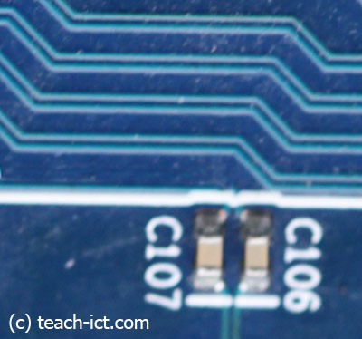
The picture below shows what an 8 bit bus actually looks like on a printed circuit board. It is usually made up of 8 conductors laid down in parallel.

Challenge see if you can find out one extra fact on this topic that we haven't already told you
Click on this link: Best 64 bit CPU
Copyright © www.teach-ict.com

